










Sauna Ventilation Guide for Homeowners and Builders
Place the fresh-air inlet above the heater and exhaust low under the bench on the opposite wall. That single rule, drawn from Finnish ventilation research and confirmed by manufacturer guidance from Harvia, covers the majority of what makes a sauna comfortable, safe, and efficient. Everything else, including sizing, fan selection, and wood-stove combustion air, builds on that foundation.
Quick-reference answers:
- Inlet location: above the heater, approximately eighteen to twenty-four inches above the top of the stones (T4 position)
- Exhaust location: low under the bench on the opposite wall, a few inches above the floor (P2 position)
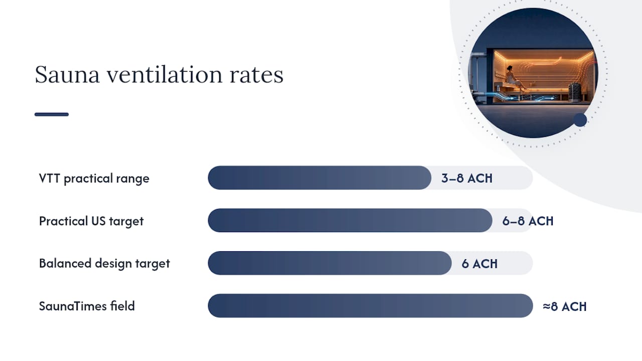
- Target airflow rate: 6 air changes per hour (ACH) as a balanced design target; acceptable range is 3–8 ACH
- Immediate next step: measure your sauna’s length × width × height in feet to get volume in cubic feet, then apply CFM = (Volume × 6) ÷ 60
Key Takeaways
Effective sauna ventilation requires the T4 inlet above the heater, a P2 exhaust low under the bench, a design target of 6 ACH, and sealed air leaks to preserve the designed flow path.
| Point | Details |
|---|---|
| T4 inlet placement | Position the fresh-air inlet 18–24 inches above the heater stones, offset from the temperature sensor. |
| P2 exhaust placement | Place the exhaust 4–8 inches above the floor under the lower bench on the opposite wall from the heater. |
| 6 ACH design target | Use CFM = (Volume ft³ × 6) ÷ 60 to size vents; the acceptable range is 3–8 ACH. |
| Wood stove combustion air | Wood stoves need a dedicated combustion-air supply; mechanical exhaust can reduce stove draft and create CO risk. |
| Saunaheatersupply products | Heater packages like the Harvia Kip45W and Saunum Air 7, plus compatible temperature probes, are available at Saunaheatersupply. |
Table of Contents
- Why does sauna ventilation affect comfort and stove performance?
- Where exactly should sauna vents be placed?
- How do you size vents and calculate CFM targets?
- How does ventilation differ for wood-burning versus electric heaters?
- Step-by-step installation checklist for sauna vents
- When do you need mechanical ventilation, and how do you control it?
- How do you diagnose and fix common ventilation problems?
- What materials and components hold up in a sauna environment?
- What did the Finnish VTT experiments actually find?
- An honest perspective on sauna ventilation tradeoffs
- Sauna ventilation products from Saunaheatersupply
- Sources
Why does sauna ventilation affect comfort and stove performance?
Good sauna ventilation is not about moving as much air as possible. It is about delivering fresh air into the breathing zone, mixing it with the heated air above the stones, and removing stale air without stripping the steam layer that creates löyly. Get that wrong and the sauna either feels stuffy and oxygen-depleted or loses its heat too fast.
The physics are straightforward. Cold incoming air is denser than the hot air near the ceiling, so it tends to sink unless it enters above a heat source that immediately mixes it upward. When the inlet sits above the heater stones, the rising convective plume from the stones catches the incoming air and distributes it across the room before it reaches the bench level. Placing the exhaust low under the bench captures air that has already passed through the breathing zone, which preserves the hot steam layer near the ceiling and upper benches where bathers sit.
Placing a main exhaust at the ceiling during a session does the opposite: it pulls the hottest, most steam-laden air out of the room immediately, dropping bench temperatures and destroying löyly. A ceiling vent has one legitimate use, which is post-session drying, and it should stay closed during bathing.
Good ventilation can paradoxically make a sauna feel hotter. When stale, oxygen-depleted air is replaced with fresh air at the breathing zone, bathers perceive the heat as more comfortable and tolerable rather than oppressive. The sensation of heat improves because breathing improves.
Harvia’s installation guidance targets a ventilation rate of multiple air changes per hour for electric saunas, a figure that aligns closely with the North American Sauna Society’s recommendation to bring supply air above the stove and remove exhaust low. The VTT 1992 experiments tested multiple inlet and outlet configurations and found that the T4 inlet (above stove) combined with P1 or P2 exhaust (low near bench) produced the best vertical temperature distribution and mixing across the room.
Where exactly should sauna vents be placed?
The T4/P2 pattern has specific dimensional targets. Getting the heights right matters more than getting the exact wall right, but wall choice still affects mixing quality.
Inlet placement (T4 position)
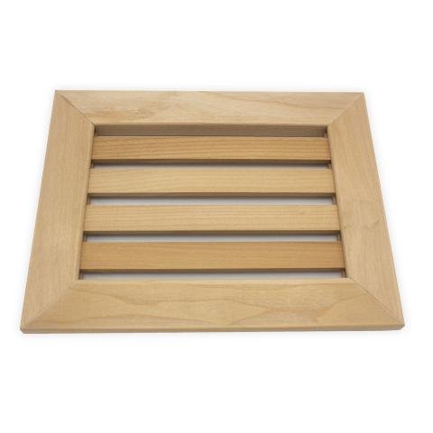
The inlet should sit on the heater wall, positioned roughly halfway between the top of the stones and the ceiling, or about 18–24 inches above the top of the heater. Harvia specifies approximately 500 mm above the stove for mechanical supply vents. This height puts incoming air directly into the convective zone above the stones, where it mixes before reaching bathers.
Do not place the inlet directly above the heater’s temperature sensor. Directing a flow of cooler supply air at the sensor causes the heater to read a falsely low temperature and overheat the room. Offset the inlet to the side of the heater rather than centered above it.
Exhaust placement (P2 position)
The exhaust goes on the wall opposite the heater, low under the lower bench, a few inches above the floor. This position captures air that has circulated through the breathing zone and cooled slightly, without pulling steam off the upper bench level. If the exhaust must exit through an adjacent washroom or mechanical chase, a door gap of roughly 1 inch at the floor can serve as a passive exhaust path, though a dedicated low vent is more reliable.
Placement checklist
- Inlet on the heater wall, 18–24 inches above the top of the stones
- Exhaust on the opposite wall, 4–8 inches above the floor and under the lower bench
- Inlet offset to the side of the heater’s temperature sensor, never centered above it
- No main exhaust at the ceiling during sessions (ceiling vent for post-session drying only)
- Avoid placing both inlet and exhaust on the same wall, which causes short-circuit flow
- Maintain at least 6 inches of clearance from any structural framing or electrical wiring when cutting openings
Common vent sizes
For most residential saunas, a round 4–6 inch diameter opening or a rectangular 4×6 to 5×6 inch opening works for both inlet and exhaust. Larger rooms (above 250 cubic feet) may need 6-inch round or 5×8 inch rectangular openings to hit CFM targets without excessive velocity. Vent grilles should be adjustable so you can reduce flow during warm-up and open fully once the target temperature is reached.
How do you size vents and calculate CFM targets?
Sizing starts with one formula and two numbers: your sauna’s volume in cubic feet and your target ACH.
CFM = (Volume in ft³ × ACH) ÷ 60
ThermalFinn recommends a minimum of 6 ACH during use, which matches Harvia’s manufacturer guidance. The VTT experimental range of 3–8 ACH gives you the outer bounds. Use 6 ACH as your design target; go to 8 ACH if the sauna is indoors with limited natural draft or if you have more than four regular bathers.
Worked example 1: small sauna (150 ft³)
A 5 ft × 6 ft × 5 ft sauna has a volume of 150 cubic feet.
- At 6 ACH: CFM = (150 × 6) ÷ 60 = 15 CFM
- At 8 ACH: CFM = (150 × 8) ÷ 60 = 20 CFM
A 4-inch round vent at low velocity handles 15–20 CFM comfortably. This is a passive-ventilation candidate if the sauna has a good natural draft path.
Worked example 2: medium sauna (300 ft³)
A 6 ft × 8 ft × 6.25 ft sauna has a volume of approximately 300 cubic feet.
- At 6 ACH: CFM = (300 × 6) ÷ 60 = 30 CFM
- At 8 ACH: CFM = (300 × 8) ÷ 60 = 40 CFM
A 5×6 inch rectangular vent or a 6-inch round vent handles airflow rates typical for medium-sized saunas at moderate velocity. At higher airflow rates, mechanical assistance may be advised for reliable performance; a small inline fan rated for 50–60 CFM gives you reliable control.
SaunaTimes’ field test measured an inlet airflow consistent with the recommendations for small electric heated saunas, which equated to roughly 8 ACH for the test sauna’s volume. That real-world data point confirms the formula works and that sealing door and frame leaks is critical: uncontrolled leaks bleed off designed flow and reduce effective ACH below what the vent size alone would suggest.
A fan rated at 50 CFM for a 30 CFM target gives you headroom without creating excessive draft.
How does ventilation differ for wood-burning versus electric heaters?
The core difference is combustion. An electric heater uses ventilation purely for air quality and mixing. A wood-burning stove needs a separate, reliable supply of combustion air to maintain draft, and that requirement changes how you design the entire ventilation layout.
Wood-burning stove requirements
Wood stoves draw air through the firebox to sustain combustion and create the chimney draft that pulls exhaust gases up and out. If mechanical exhaust reduces the pressure inside the sauna, it can compete with the stove’s draft, causing incomplete combustion, smoke spillage, or carbon monoxide buildup. The risks include:
- Stove choking: insufficient combustion air causes the fire to smolder rather than burn cleanly
- Backdrafting: negative pressure pulls flue gases back into the room
- Carbon monoxide accumulation: a real safety hazard that requires a CO detector in any wood-stove sauna
For wood stoves, the North American Sauna Society recommends natural gravity ventilation rather than mechanical exhaust. A low inlet near the stove floor provides combustion air directly to the firebox, and a high outlet near the roof allows hot exhaust air to escape by natural convection. If mechanical exhaust is used, it must be adjustable and sized so it does not reduce stove draft below the manufacturer’s minimum requirement. Consult the stove manufacturer’s installation manual for the minimum combustion-air opening size.
Electric heater requirements
Electric heaters have no combustion, so the only ventilation goal is air quality and mixing. The T4 inlet above the heater and P2 exhaust under the bench work exactly as described. The one caution specific to electric heaters is sensor placement: do not direct supply airflow at the heater’s temperature sensor. A stream of cooler air hitting the sensor causes the controller to read a false low temperature, which drives the heater to overheat the room.
Pro Tip: If you are installing a heater with an external temperature probe, such as those compatible with iSteam, AirTempo, iTempo, and iTempoPlus controls, position the temperature probe at bench height on a side wall, away from both the inlet airstream and the heater body. This gives you an accurate reading of the breathing-zone temperature rather than the heater-surface temperature.
When to hire a specialist
Call an HVAC or combustion specialist when:
- You are installing a wood-burning stove and need to balance combustion air with whole-house mechanical ventilation
- The sauna is inside a conditioned building where depressurization could affect other combustion appliances (furnace, water heater)
- Local building codes require a permit and inspection for the flue or combustion-air opening
- You cannot establish reliable draft after following the manufacturer’s installation instructions
Step-by-step installation checklist for sauna vents
A safe installation sequence runs: measure and confirm clearances, mark openings, cut, install screened and damped fittings, seal, and test airflow. Do not cut before you have confirmed heater clearances and checked for wiring or framing in the wall.
Tools and materials
- Hole saw set (4–6 inch) or jigsaw for rectangular openings
- Stud finder and voltage tester
- High-temperature silicone caulk (rated to at least 400°F)
- Stainless steel vent grilles with adjustable dampers
- Back-draft dampers (stainless or aluminum, spring-loaded)
- Insulated sauna duct sleeves for any duct runs through wall assemblies
- Smoke pencil or incense sticks for airflow testing
Installation steps
- Measure the sauna volume and calculate your CFM target using the formula above. Confirm the vent sizes you need before cutting anything.
- Locate the heater wall inlet position: mark the center of the inlet opening 18–24 inches above the top of the heater stones, offset to the side of the temperature sensor. Use a stud finder to avoid framing; use a voltage tester to confirm no wiring is present.
- Locate the exhaust position: mark the center of the exhaust opening on the opposite wall, 4–8 inches above the floor and below the lower bench line.
- Cut the inlet opening with a hole saw or jigsaw. Work from the interior face of the wall. Cut cleanly to avoid splintering the interior paneling.
- Cut the exhaust opening using the same method.
- Install duct sleeves through the wall thickness if the wall is insulated. Insulated sleeves prevent condensation inside the wall cavity and protect the duct from moisture.
- Fit the interior grilles with adjustable dampers so you can control flow during warm-up and open fully during the session.
- Fit the exterior covers with back-draft dampers to prevent cold outside air from entering when the sauna is not in use.
- Seal all gaps between the duct sleeve and the wall framing with high-temperature silicone caulk. Unsealed gaps bleed off designed airflow and reduce effective ACH.
- Test airflow with a smoke pencil or lit incense stick held near the inlet and exhaust. You should see clear movement toward the exhaust within 30–60 seconds of the heater reaching operating temperature. No movement indicates a blockage, a sealed damper, or insufficient pressure differential.
Safety checks before first use
- Confirm all electrical wiring is at least 6 inches from vent openings and duct sleeves
- Verify the heater’s temperature sensor is not in the direct path of the inlet airstream
- For wood stoves, confirm the chimney draws correctly with the sauna door closed and the combustion-air inlet open
- Install a CO detector near the floor level in any wood-stove sauna before the first fire
When do you need mechanical ventilation, and how do you control it?
Natural convection handles ventilation in many small outdoor saunas, but it has limits. Use mechanical exhaust when the sauna is large (above 250 cubic feet), located indoors without a clear natural draft path, or when passive testing shows insufficient airflow at the exhaust.
Fan selection
- Choose fans rated for continuous operation at the expected exhaust temperature. Exhaust air from a sauna can reach 140–160°F at the low exhaust position; standard bathroom fans are not rated for this.
- Place fans outside the heated sauna volume, either in an adjacent mechanical space or in the duct run after it exits the sauna wall. Running a fan inside the hot cube exposes the motor and electronics to conditions that shorten service life and create a fire risk.
- Size the fan at 20–25% above your CFM target to account for duct resistance. For a 30 CFM target, a fan rated at 50 CFM gives adequate headroom.
- Inline duct fans rated for high-temperature operation (look for ratings above 140°F continuous) are a practical choice for sauna exhaust.
Control strategies
- Simple timer control: a 60-minute mechanical timer turns the fan on at session start and off after a post-session purge period of 10–15 minutes. This is the most common and reliable approach for residential saunas.
- Variable-speed control: a variable-speed wall controller lets you reduce flow during warm-up (when you want to build heat quickly) and increase it during the session. This is worth the added cost for larger saunas where draft control matters.
- Interlock with heater control: some Wi-Fi heater controllers can trigger a fan relay, running the fan automatically when the heater is on. Check compatibility with your specific heater model before wiring this.
- Avoid placing fan speed controllers or timers inside the sauna. All controls should be outside the heated space.
When integrating sauna exhaust into a whole-house mechanical ventilation system, hire an HVAC contractor. The sauna’s exhaust air is hot and humid, and it needs to be isolated from supply-air paths to prevent moisture damage and heat transfer to other zones.
How do you diagnose and fix common ventilation problems?
Most ventilation problems fall into a short list of causes: wrong vent placement, undersized openings, sealed or blocked dampers, or air leaks that short-circuit the designed flow path.
| Symptom | Likely cause | Fix |
|---|---|---|
| Stove choking or weak fire | Insufficient combustion air or overpowered exhaust fan | Open or enlarge combustion-air inlet; reduce or remove mechanical exhaust |
| Uneven bench temperatures (top bench much hotter than lower) | Inlet too low or exhaust too high; poor mixing | Raise inlet to T4 position above heater; lower exhaust to P2 under bench |
| Stuffy or oxygen-depleted air | Insufficient ACH; sealed dampers or air leaks bypassing designed path | Open dampers fully; seal frame leaks; verify CFM meets 6 ACH target |
| Condensation on walls or ceiling | Insufficient post-session purge; no ceiling vent for drying | Open ceiling vent after bathing; run exhaust fan for 15 minutes post-session |
| Persistent odors | Stagnant air pockets; exhaust not capturing breathing zone | Reposition exhaust lower; add small mixing vent near floor on heater wall |
| CO detector activation | Backdrafting from wood stove; combustion air deficit | Stop using stove immediately; call a combustion specialist before next use |
Quick fixes worth trying before calling a pro: open both dampers fully and retest with a smoke pencil, seal visible door and frame gaps with weatherstripping, and check that the exterior back-draft damper is not frozen or stuck closed. Sealing air leaks materially improves ventilation effectiveness, and it costs nothing.
Red-flag situations that require professional attention before the sauna is used again:
- CO detector activation at any level
- Visible smoke or backdrafting from a wood stove
- Inability to establish any draft after following the manufacturer’s instructions
- Persistent strong chemical or burning odors from the heater or duct
What materials and components hold up in a sauna environment?
The sauna environment combines temperatures up to 200°F, high humidity, and repeated wet-dry cycles. Standard galvanized steel grilles, PVC duct fittings, and foam-based sealants fail quickly under these conditions.
Recommended components
- Grilles and screens: stainless steel (304 or 316 grade) for interior-facing grilles; aluminum is acceptable for exterior covers where it is not exposed to direct steam
- Back-draft dampers: stainless steel spring-loaded dampers rated for high temperature; avoid plastic-blade dampers, which warp and stick
- Duct sleeves: aluminum sauna duct sleeves or rigid aluminum duct for runs through wall assemblies; flexible aluminum duct is acceptable for short runs outside the heated space
- Sealants: high-temperature silicone rated to at least 400°F; standard latex or acrylic caulk softens and fails at sauna temperatures
- Fasteners: stainless steel screws for any hardware inside the sauna; standard zinc-plated screws corrode within one to two seasons
Pro Tip: When routing duct through an insulated wall, use a telescopic sauna duct sleeve that adjusts to your exact wall thickness. These sleeves are designed for the thermal expansion that occurs as the sauna heats and cools, and they prevent the cracking and gap formation that rigid fixed-length sleeves develop over time.
Maintenance schedule
- After each session: open the ceiling vent or exhaust damper for 15–20 minutes to purge residual humidity and allow the sauna to dry
- Monthly: inspect grille faces for lint, dust, or mineral deposits; clean with a dry brush or low-pressure air
- Seasonally: check back-draft dampers for free movement; inspect sealant around duct sleeves for cracking or separation; verify that exterior covers are not blocked by debris or ice
- Annually: remove interior grilles and inspect the duct sleeve interior for mold or mineral buildup; replace any sealant that shows cracking or discoloration
What did the Finnish VTT experiments actually find?
The 1992 VTT study by Erkki Äikäs and Rolf Holmberg remains the most-cited primary source for sauna ventilation placement. The researchers tested multiple inlet and outlet configurations in an instrumented test sauna and measured temperature distribution, mixing quality, and perceived air quality across each configuration.
The core finding was clear: supplying fresh air above the stove (T4 position) and removing it low near the bench (P1 or P2 position) produced the best vertical temperature distribution and the most uniform mixing. Configurations with ceiling-level exhausts during use pulled the hottest air out immediately and created steep vertical temperature gradients, with the upper bench much hotter than the lower bench and the footboard area cold. The T4/P2 pattern flattened that gradient and improved footboard temperatures, which is a direct measure of mixing quality.
The VTT experiments found that inlet placement above the stove (T4) combined with low exhaust near the bench (P1/P2) improved both vertical temperature distribution and air quality. The practical ventilation range supported by the test data runs from roughly 3 to 8 air changes per hour, with the best comfort results in the middle of that range.
The study also documented the effect of air leaks. Uncontrolled leaks through door frames and wall penetrations reduced the effectiveness of the designed flow path, confirming that sealing matters as much as vent placement.
SaunaTimes’ field test measured an inlet flow of approximately 35 CFM in a real home sauna, equating to about 8 ACH for that room’s volume. The field data aligned with the VTT range and confirmed that 6–8 ACH is a practical U.S. target for electric Finnish-style saunas.
| Configuration tested | Vertical temp. distribution | Mixing quality | Notes |
|---|---|---|---|
| T4 inlet + P2 exhaust (low under bench) | Good, even gradient | Strong | Recommended configuration |
| T4 inlet + ceiling exhaust | Poor, steep gradient | Weak | Löyly lost; upper bench overheats |
| Low inlet + low exhaust (same wall) | Poor | Short-circuits | Stale air pockets at bench level |
| Low inlet + P2 exhaust (opposite wall) | Moderate | Moderate | Acceptable fallback; less mixing than T4 |
The practical takeaways from the VTT work and subsequent field reports are consistent: use T4 for the inlet, P2 for the exhaust, seal air leaks, and design for 6 ACH as a balanced target. The full VTT report is available through the SaunaTimes document archive for readers who want the original temperature measurement data.
An honest perspective on sauna ventilation tradeoffs
The single most important rule in sauna ventilation is also the most frequently violated: keep the vents open during the session. Builders and homeowners close dampers to preserve heat during warm-up, then forget to reopen them. The result is a sauna that gets hot but feels suffocating after 10 minutes.
The second most common mistake is placing the inlet too low, either at floor level or below bench height, because it feels intuitive to bring fresh air in at breathing level. Cold air entering at floor level sinks and pools without mixing, creating a cold footboard and a hot, stale upper bench. The T4 position above the heater feels counterintuitive because you are bringing cold air in near the hottest point in the room, but that is exactly what drives the convective mixing that makes the whole system work.
Over-sealing is a real problem in well-insulated saunas. Builders who follow good insulation practice sometimes seal the sauna so tightly that passive ventilation cannot establish any pressure differential. If your smoke test shows no movement at the exhaust after 60 seconds, the sauna is too tight for passive ventilation and you need a small mechanical exhaust fan. Accept the modest energy cost; the alternative is a sauna that is uncomfortable and potentially unsafe.
For wood stoves, the combustion-air question is not optional. A wood stove in a tightly built indoor sauna without a dedicated combustion-air supply is a CO risk. If you are comparing wood-burning and electric heater options for a new build, factor in the added complexity and cost of combustion-air planning for wood stoves. Electric heaters eliminate that risk entirely and give you more flexibility in ventilation design.
The tradeoff between slightly higher heat loss and much better comfort and safety always resolves the same way: a properly ventilated sauna with a small amount of heat loss is a better sauna than a sealed one that feels oppressive. Design for 6 ACH, keep the dampers open, and the heat loss is manageable.
Sauna ventilation products from Saunaheatersupply
Saunaheatersupply stocks heaters, Wi-Fi controllers, and temperature probes selected to work within the ventilation constraints described in this guide. For homeowners building a new sauna, the Harvia Kip45W Heater Package with Wi-Fi and stones is a strong starting point: it includes the heater, controller, and stones in one package, and its sensor placement follows the offset-from-inlet guidance Harvia specifies. For larger rooms or those wanting integrated air-mixing technology, the Saunum Air 7 Sauna Heater Package and the Saunum Air L 15 Package are built around Saunum’s air-equalization system, which actively circulates air to reduce the vertical temperature gradient that poor ventilation creates.
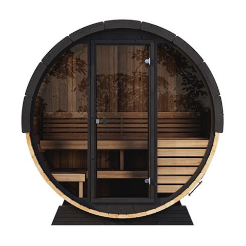
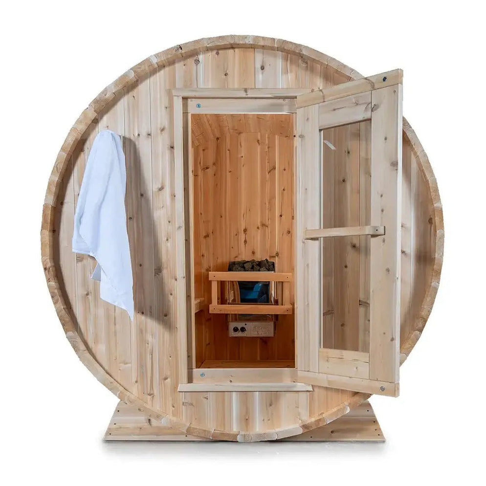
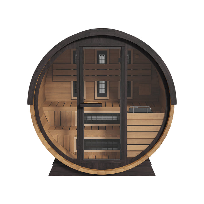
For steam shower applications, the iSteamX Steam Shower Control and Steamhead and the iTempo Round Steam Shower Control and Steamhead are compatible with the Temperature Probe for iSteam, AirTempo, iTempo, and iTempoPlus Controls, which lets you position the sensor at bench height away from the inlet airstream. For outdoor barrel sauna builds, the Finnmark Thermo-Aspen Combination Barrel Sauna FD-7 and the Finnmark Cedar Combination Barrel Sauna FD-6 come as complete kits with pre-designed ventilation openings. The IKI Pillar 9kW with Wi-Fi Controller Glass suits larger rooms where a higher-output heater is needed alongside careful sensor placement.
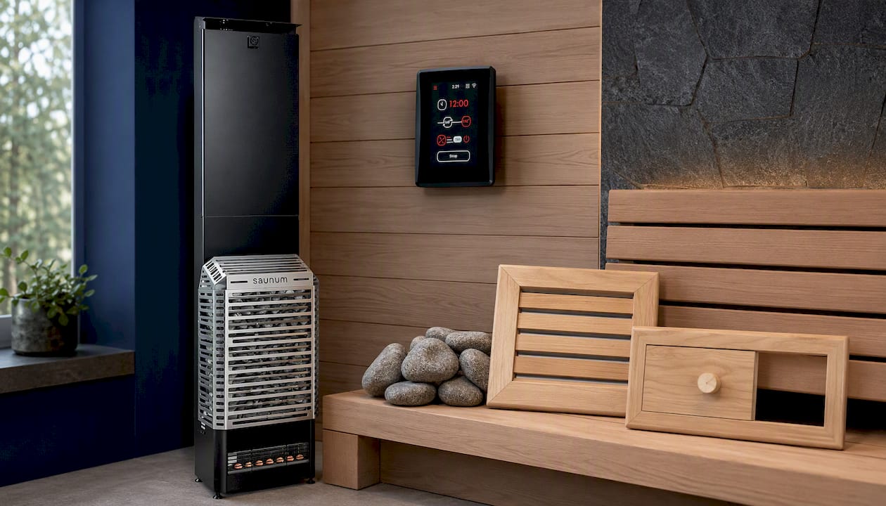
Contact Saunaheatersupply’s product team for help matching a heater package to your room volume and ventilation layout. Browse the full catalog at Saunaheatersupply or reach out directly for sizing guidance before you cut any openings.
Sources
- 3333333VTT INFORMATION 1431 Erkki Äikäs & Rolf Holmberg Sauna temperatures and ventilation
- Ventilation in the sauna
- Sauna Air Quality — The North American Sauna Society
Recommended
- Sauna Heater Installation: Step-by-Step Guide for Homeowners — Sauna Heater Supply
- Steam Room vs Sauna: What Homeowners & Contractors Should Choose — Sauna Heater Supply
- Sauna Ceiling Height: Exact Measurements for Builders — Sauna Heater Supply
- Sauna Power Requirement | Electrical Planning for Installation — Sauna Heater Supply